Integration examples
Gimbal
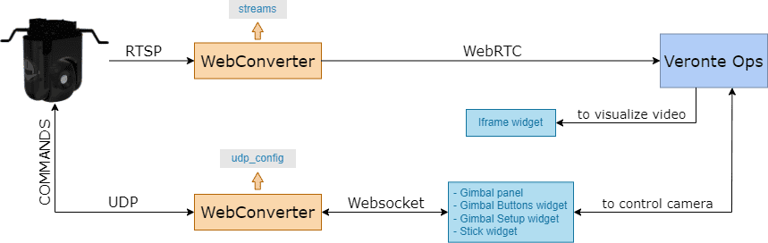
The following diagram summarizes the "connection" and "elements" required to view video recording and/or command a generic gimbal in Veronte Ops:
Note
The configuration described in this section covers how to set up and control a generic gimbal with Veronte Ops.
To configure and control a gimbal from Veronte Ops, the following must be considered:
- The gimbal must be configured in the Gimbal panel.
- Use the Gimbal Buttons widget to command actions to the gimbal camera.
- Use the Gimbal Setup widget to configure some options of the gimbal camera video.
- To view the video recording and/or track directly with the displayed image, the Iframe widget is needed.
- Finally, if the user wants to manage the gimbal with a Veronte Ops virtual stick or a USB joystick, the Stick widget must also be configured.
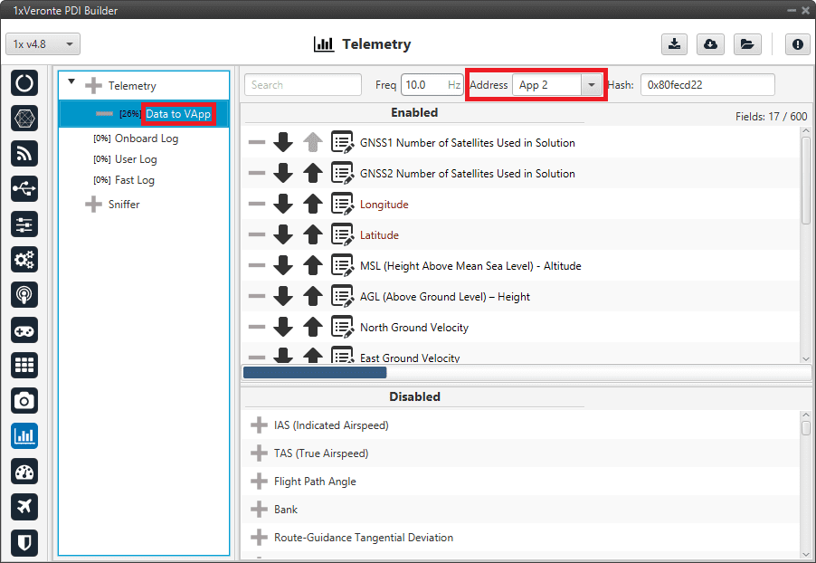
Furthermore, it is necessary to configure the following variables in the telemetry vector of the Autopilot 1x in order to establish a correct communication for commanding between Veronte Autopilot 1x Veronte Ops Gimbal:
- GNSS2 Number of Satellites Used in Solution
- GNSS1 Number of Satellites Used in Solution
- Longitude
- Latitude
- MSL (Height Above Mean Sea Level) - Altitude
- AGL (Above Ground Level) - Height
- North Ground Velocity
- East Ground Velocity
- Down Ground Velocity
- Heading
- GS (Ground Speed)
- p (Angular Velocity - X Body Axis)
- q (Angular Velocity - Y Body Axis)
- r (Angular Velocity - Z Body Axis)
- Yaw
- Pitch
- Roll
The Data to Vapp telemetry vector in the Autopilot 1x configuration (using 1x PDI Builder software) should look like this:
Veronte Gimbal
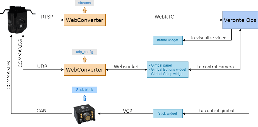
The following diagram summarizes the "connection" and "elements" required to view video recording and/or command a Veronte Gimbal in Veronte Ops:
Note
The configuration described in this section covers how to set up and control a Veronte Gimbal with Veronte Ops.
To configure and control a Veronte Gimbal from Veronte Ops, the following must be considered:
-
The gimbal must be configured in the Gimbal panel. If the user has a Veronte Gimbal 10z, the configuration should look like this:
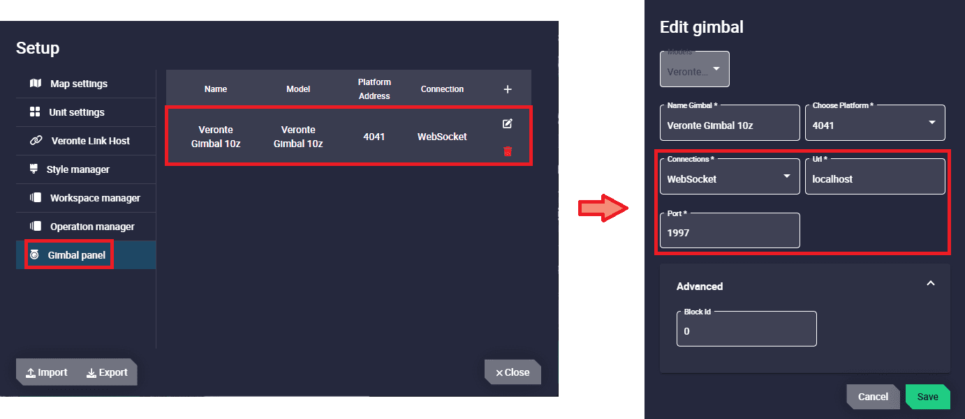
Veronte Gimbal configuration - Gimbal panel - Model: Veronte Gimbal 10z
- Connections: Websocket
- Url:
websocket_urlconfigured in the Web Converter app. - Port:
websocket_portconfigured in the Web Converter app.
-
Use the Gimbal Buttons widget to command actions to the gimbal camera. For the Veronte Gimbal 10z, the following actions are available:
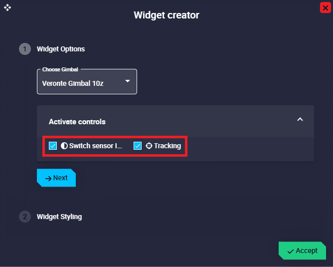
Veronte Gimbal configuration - Gimbal Buttons widget - Switch sensor IR/Day: Button to switch between IR and EO camera.
- Tracking: Button to stop tracking.
-
Use the Gimbal Setup widget to configure some options of the gimbal camera video. For the Veronte Gimbal 10z, the following controls are available:
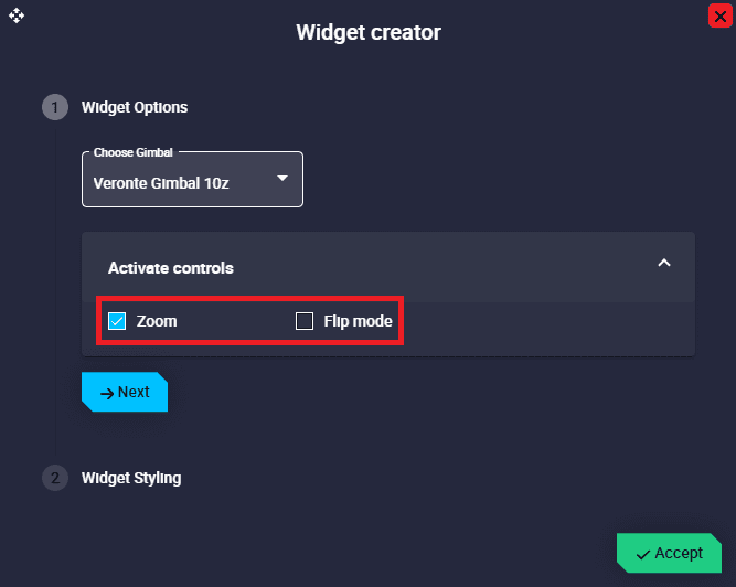
Veronte Gimbal configuration - Gimbal Setup widget - Zoom: Users can zoom from 0% to 100% with a slider.
- Flip mode: Users can flip the camera as desired. The available options are Normal, Mirror, Flip and Mirror and flip.
-
To visualize the video recording and/or track directly with the displayed image, the Iframe widget is needed.
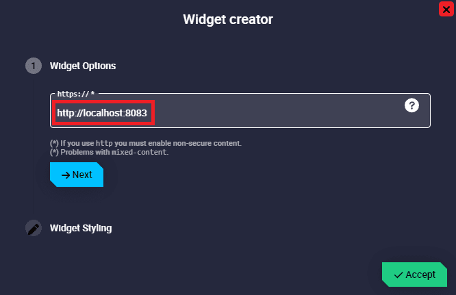
Veronte Gimbal configuration - Iframe widget - https://: Enter the URL generated by the Web Converter app.
-
Finally, to control the gimbal with a Veronte Ops virtual stick or a USB joystick, the Stick widget must also be configured as shown in the figure below:
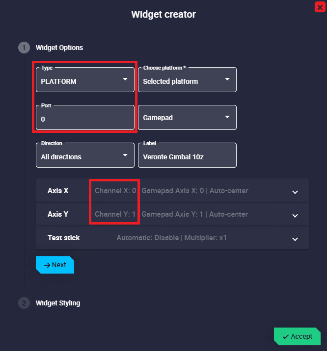
Veronte Gimbal configuration - Stick widget Note
In this case, it is controlled directly with the virtual stick (no USB joystick is being used).
- Type: PLATFORM must be selected.
- Port: Select the port configured in the Stick block in the 1x PDI Builder software.
- Axis X/Y: Configure both channels X and Y.
Stick widget
Once the steps described in the Stick widget - Integration examples section of the 1x PDI Builder manual have been performed, configure Veronte Ops to enable the commands of the Stick widget. To do so:
-
Add a Stick widget.
Note
The connection should work with the default settings. For more information on the configuration of the Stick widget, please refer to Stick - Workspace section of this manual.
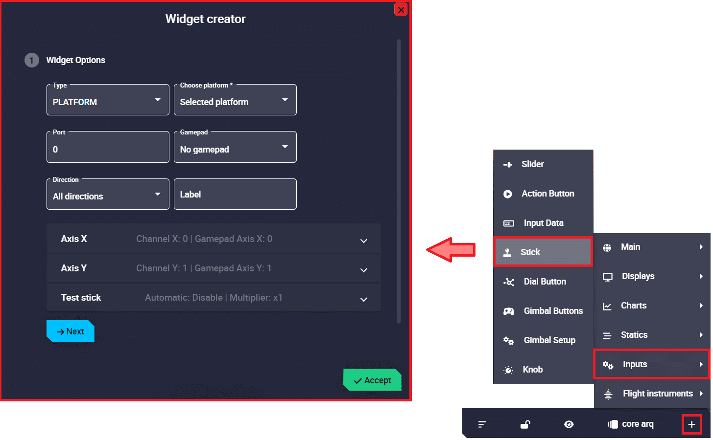
Stick widget - Stick configuration -
Enable the send of commands to Veronte Autopilot by clicking on the Send command button of the widget.
Stick widget - Enable send commands
USB joystick
Veronte Ops is able to detect USB devices such as joysticks. The buttons and axes of these devices can be read and configured to send stick information to Veronte Autopilot 1x.
Once the steps described in the USB joystick - Integration examples section of 1x PDI Builder manual have been performed, configure a Stick widget to be connected to a USB joystick. To do so, follow the steps below:
- Select the Gamepad that corresponds with the USB joystick connected to the PC.
-
And configure the Gamepad Axis X/Y ID so that the axes IDs of the stick widget gamepad correspond to those of the physical joystick.
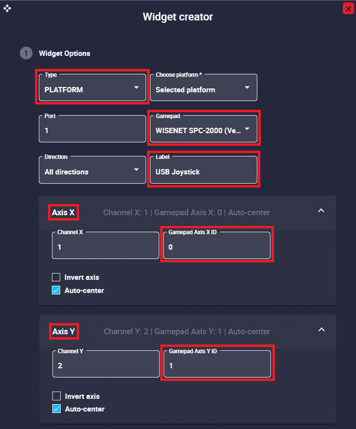
Stick widget - USB joystick -
Enable the send of commands to Veronte Autopilot by clicking on the Send command button of the widget.
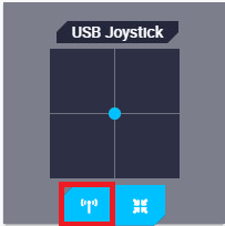
Stick widget - Enable send commands
Below is an example of how the stick widget works with the previous configuration:
© 2026 Embention. All rights reserved.